Simple Demonstration of KIEF
Overview
Design in KIEF is conducted by using the pluggable metamodel mechanism.
For starting a design from the functional specification, the
design process has the following four steps.
-
Functional Design on FBS modeler
FBS modeler takes required functions as inputs. FBS modeler decomposes
the required functions into subfunctions in order to detail it using functional
knowledge. As a result, a functional hierarchy is constructed. After that,
each function located at the bottom of the function hierarchy are realized
with physical features that is a building block of metamodel.
-
Computing a metamodel
The metamodel mechanism finds out possible physical phenomena that
may occur on the design object with qualitative reasoning.
-
Generating an external model
The designer generates an aspect model for evaluation by an external
modeler. First, the metamodel mechanism selects related concepts to the
aspect and relations among the concepts from the metamodel. By doing so,
a conceptual model for generating an external model is constructed. After
this, the metamodel mechanism translates the conceptual model to an external
model by using model fragments and attribute data represented in the metamodel.
Click
here for detail description of modeling process.
-
Evaluating the external model
Finally, the designer evaluates the generated aspect model with the
external modeler.
The last 2 steps reiterate for evaluating from various aspects.
Functional Design on FBS modeler
At beginning of the design process, designer uses the FBS modeler to do
functional design.
Function Decomposition
Function decomposition is a process to build a function hierarchy from
the top functions given by the designer. The knowledge of developing
methods in function prototypes is used by FBS Modeler to assist the
designer.
And then, the designer inputs one or more needed function as shown in
Figure
1. In this figure, the large window which includes
Function Layer
and Behavior Layer is the main workspace for constructing an FBS
model, the Function Prototypes window depicts a list of the function
prototypes, and the Features for This Function
depicts a list of
the physical features connected to a selected function. Here, the designer
instantiates the needed function ``exMove (table)'' .

Figure 1: Selection of Needed Function
Then, the designer constructs a function hierarchy by decomposing the
needed function by using appropriate developing methods defined
in
the function prototypes (see Figure 2). Here,
the black lines, such as the relation between ``move'' and ``rotate,''
represent super-sub relations in the function hierarchy. Of course, you
can construct the function hierarchy without using the developing methods
by instantiating some function prototypes and connecting them.
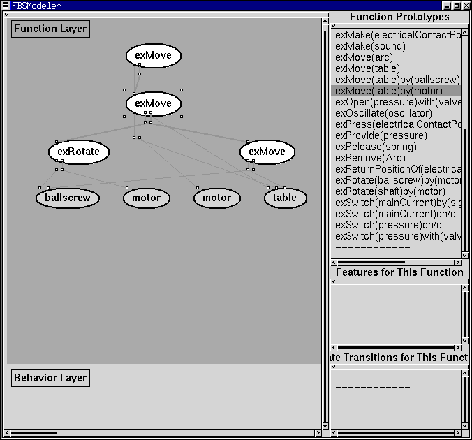
Figure 2: Construction of Function Hierarchy
Selection of Physical Features
As the second step, from the bottom functions of this function hierarchy,
physical features will be derived, and by combining these
physical features a primary model for the design object that realize
the target function will be constructed. There are two ways to get
physical features for each bottom functions. One is to directly
select some physical features written in the function prototypes as
knowledge, and the other is to create physical features from the behaviors
which may be also written in the function prototypes.
The designer can select physical features for realizing the function
hierarchy.
Figure 3 shows the result of this selection.
Namely, the designer chooses one of the functions in the lowest level of
the function hierarchy. In Figure 3, selected physical features are derived
and decomposed into the concept dictionary elements (entities, relations,
and physical phenomena) in the Behavior Layer. Thin arrows among
the concept dictionary elements depict the physical dependencies, and dotted
thick lines depicts which concept dictionary element derived from which
function.
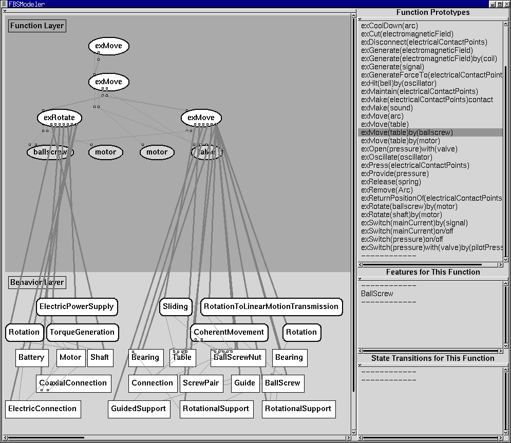
Figure 3: Selection of Physical Features
Creation of Physical Features
Instead of selecting physical features directly, the designer can create
some physical features from the behaviors attached to the function prototypes
so that the designer can construct the design object model more flexibly.
QPAS
(Qualitative Process Abduction System) interface supports this operation
(Figure 4).The QPAS interface can suggest physical
phenomena which entail the desired behavior by using the influence information
of physical phenomena. This interface creates new physical feature by combining
existing physical feature to invoke desired physical phenomena.

Figure 4: The QPAS Interface
Delegation
Since the physical features generated in the previous step are independent
with each other, the designer should construct a consistent design object
model, which is called as a primary model in the metamodel system.
This is done by identifying same entities included in more than one physical
feature. This manipulation is called delegation.
Delegation is the method to make an instance of entity which has more
than two views. In a physical feature, each of entities has a certain
view which depends on the physical feature. Therefore, when the designer
combines several physical features, there may be some entities which are
identical but described from different views. In the FBS modeler, this
is done by delegation. For example, since ``Shaft'' and ``BallScrew''
in Figure 3 should be identical, the designer delegates
these two (see Figure 5).

Figure 5: Example of Delegation
Computing a Metamodel
As a result of the previous steps, a function hierarchy and a primary model
of the design object are constructed. Since it can be physically inconsistent,
this must be checked. For checking physical consistency,
behavior simulation can be executed by using other modelers. To use
other modelers, the designer propagate the FBS model to the pluggable metamodel
mechanism. After propagating the FBS model, the metamodel mechanism reasons
out possible physical phenomena occurred on the design object by using
physical feature knowledge base.
Generating and Evaluating with an
External Model
Evaluation with the Qualitative Reasoning System
Make new aspect model for qualitative reasoning system.
First, physical phenonmena and attributes informations are selected
from metamodel to generate aspect model for qualitative reasoning system.
From these information, this method creates parameter network model
by applying model library for the system (Figure 6).

Figure 6: Parameter Network Model for Qualitative Reasoning System
-
Export model from the metamodel mechanism
-
Accept parameter network model
The designer accepts parameter network model in Qualitative Reasoning
system. At that time, parameters which have no relation with other parameters
are neglected. If he/she does not satisfy the exported model, he/she
can modify the parameter network manually.
-
Modify landmark of each parameter
He/she opens the landmark modeler and checks the setting of parameter
space by using this modeler. If he/she does not satisfy the parameter space,
he/she can modify the parameter space.
-
Behavior simulation
To execute behavior simulation, he/she constructs ATMS model for the
design object. An envisioner opens and the designer can run behavior reasoning
called envisioning. Figure 7 shows envisioning
result.
-
Propagate result to the metamodel mechanism

Figure 7: Envisioning Result
Evaluation with the FBS Modeler
The designer can evaluate the constructed the FBS model by comparing it
with the result of simulation by exporting the result from the metamodel
by using Aspect Modeler.
To evaluate the result of the qualitative reasoning system, the designer
should describe the conditions which describes a function is considered
to be realized. These conditions can be described in any function nodes.
In the example, since the needed function ``exMove (table)'' can be considered
to be realized when the position of the table moves from its initial position,
the designer sets the condition by writing ``(Table position) > zero.''
This expression should be ``(entityName parameterName) *
parameterValue''
(* should be >, <, or =) and the user can write more than one such expressions
in a condition window (they are parsed as and conditions).
By using this information, the system indicates the following information
(see Figure 8).
-
Unrealizable physical phenomena
If physical phenomena described by the designer do not occur in the
simulated result, some conditions should be inadequate. They are depicted
as black rectangular nodes.
-
Side-Effects
Physical phenomena that are not expected to occur in the simulation
may cause side-effects that the designer did not notice. These are added
physical phenomena shown as hatched rectangular nodes.
-
Unrealizable functions
If functions have unrealizable views in their F-B relationships, unrealizable
subfunctions, or their conditions described above are not satisfied in
the simulated network, they will not be realized. They are depicted as
black oval nodes. Moreover, the designer can know why the function
is unrealizable in the Reason window.
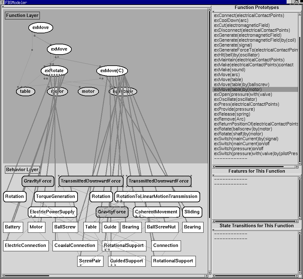
Figure 8: Consistency checking in the FBS modeler
Unless satisfied with the result of evaluation, the designer repeatedly
refines the function hierarchy and/or the view network. As a result, the
FBS Modeler outputs the basic structure of the design object.
Evaluation with the Beam Modeler
Side effect phenomena, such as ``GravityForce'', ``TransmittedDownwardForce''
brings, the designer to notice that deformation might be important and
he/she evaluates the deformation of the ballscrew with the beam model.
Then the metamodel mechanism prepares abstract components for building
a beam model; i.e., beam, distributed force, support, and so on (Figure
9).
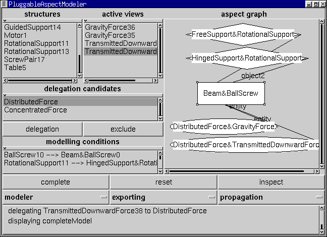
Figure 9: Qualitative Beam Model of the Ballscrew
However, because at this stage there is no numerical information about
the structure (length of beam, position of support, etc.), the metamodel
mechanism cannot generate the beam model. Therefore, the system selects
the appropriate modelers to handle these numerical information. In this
case, the system selects the 2D draw modeler and the solid modeler with
the knowledge about modelers. Then, the designer inputs shape data with
one of these modelers (Figure 10). After inputting
shape data, the system supplies the data to the beam modeler. Since it
is difficult to determine the axis of beam automatically in this case,
the system requests the designer to specify the axis of the beam. Finally,
new beam model is generated.

Figure 10: Geometric Model of the Mechanism
((a) solid model (b) 2D draw)
Figure 11 depicts the shearing force diagram of the
ballscrew computed by Mathematica.
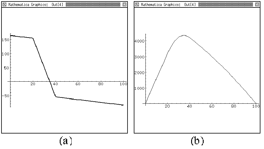
Figure 11: Result of the Beam Model
(a) Sharing force diagram (b) Bending Moment Diagram
Back to KIEF main page